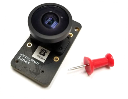
One of the most common questions Sunex receives is regarding the need for Active Alignment of lens modules. Initially, customers designing or prototyping an imaging system may find it hard to see the value of actively aligned modules. After all, active alignment requires a significant tooling investment. In addition, during the prototyping phase, customers can typically achieve great results in small numbers by manually focusing the lens and gluing it into an off-the-shelf camera module. This blog post will attempt to explain the value of Active Alignment, and the use of AA to align lens modules in a production environment.
The value of Active Alignment (AA) lies in compensation for tilt. Active alignment is used to compensate for boresight error within the accuracy of the testing machine (down to ~.05°).
Sunex typically recommends active alignment for imaging requirements of >3 – 5MP or for sub 2um pixel pitch. Pairing a high-quality, precision optic with an imprecise alignment method may not fully realize the performance, especially edge MTF, that the lens itself is capable of delivering on a consistent basis.
In theory, a threaded version of a module can produce a module with performance equal to an AA version of that same module, but the statistical population of such a result in mass production will be very low. The results are not consistent because of tilt. This matters most in high-resolution applications and in larger quantities where yield is a major contributor to cost and cycle time.
The lens design and sensor selection is not necessarily the root issue, as are other external factors.
Factors contributing to tilt:
- Barrel design: mechanical axis to optical axis (bore)
- Holder design: mechanical axis (bore) to base flatness and perpendicularity)
- Individual thread pitch (wobble, tilt, backlash)
- PCB Board design (flatness, thermal behavior)
- PCB + SMT (BGA or backplane flatness)
- Sensor glass height and tilt
- Operating Temperature effects
- Other factors and tolerances present during the final assembly of the module
Threaded modules are typically focused manually by an operator using an optical SFR score, or a resolution target. The manual nature of the focusing process, combined with the use of threads of alternating height on a barrel will limit a module’s full capabilities at higher resolution. Threaded modules are typically capable of alignment to about 1° tilt on average. Depending on the size of the sensor and the pixel pitch, this may translate to a depth of focus issue at the edges or corners of the image. By contrast, active alignment actively compensates for tilt in each individual module to within a fraction of a degree (<20’ / 0.3° typical).
Bearing in mind that Sunex usually recommends AA for systems of 3 – 5 MP or greater resolution, we can now look at a more extreme example of a 20MP module to better demonstrate tilt compensation on an AA module vs threaded module. Below is an MTF simulation of a recent 20MP module design shown with varying degrees of tilt in alignment. A typical AA module would be represented by 0’ – 20’ while a typical threaded alignment is represented by 60’ or 1°.

While it can be difficult to simulate real-world results which take into account all factors, the typical resulting “net” tilt with AA is approximately an order of magnitude better than what we can typically expect from a manually aligned module.


One Response