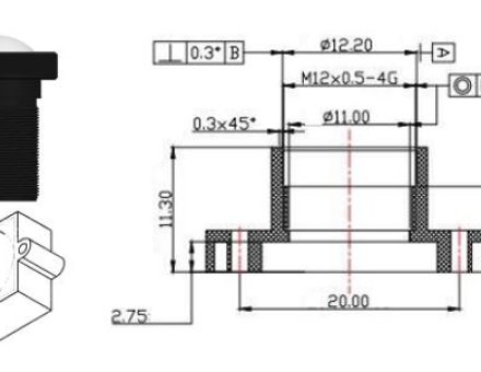
At Sunex, we get many questions about lens and mount (holder) threads when it comes to board-mount lenses. In this post, we will explore some of the basic considerations of the threaded lens and mount combinations, as opposed to some other common methods, which we will touch on. Although this post will not be a detailed tutorial of the mechanical engineering theory of thread specifications, a basic understanding of thread spec and tolerance helps to understand the considerations involved. Likewise, the advantages or disadvantages of choosing one mounting method over another will not be discussed here but will be covered in a future post.
Basics of Thread Tolerance:
ISO Threads are defined by the nominal diameter of the thread, such as M8, M10 or M12. These specific examples were intentionally chosen as they are the most common board-mount lens types. These then represent lenses whose nominal diameter at the thread section is 8mm, 10mm, and 12mm, as shown below in Figure 1. M12 in particular is an extremely common thread size for general-use lenses in applications such as Security, Automotive, Video-Conferencing, Drones, and Computer Vision applications.
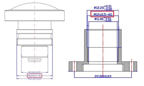 Figure 1 – Lens and Mount Thread Specifications
After defining thread diameter, it is necessary to define the thread pitch. Pitch, as you probably surmised, is the distance between the peaks (or valleys) of the thread teeth; see Figure 2. To avoid binding, it is imperative that the pitch of the thread match the pitch of the holder. Most commonly, M8 lenses are 0.35mm pitch and M12 lenses are 0.5mm pitch, although any combination is possible and maybe customizable, depending on the application. Once thread size and pitch are defined, this is enough to nominally define the thread spec but is not enough to produce actual parts or to ensure a good fit. This is because, as always, mechanical tolerances dictate how loosely or tightly the parts fit. In the case of thread fit, however, it is unfortunately not as simple as a smooth inner vs outer bore fitment because there are effectively many mating surfaces involved. There are also issues unique to the thread, such as backlash or “wobble”. More on this later, but for now, we must understand that in addition to thread diameter and pitch, there are also ISO thread tolerance “bands” which contribute to fit and are illustrated below in Figure 3. Note that internal threads are always Capital letters and external are lower-case. Also take note that although the threads do not (and cannot) overlap, there are line-to-line combinations possible in the spec. Taken together, we can see the full thread spec as it applies to lenses and mounts in Figure 4.
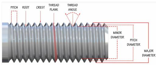
Figure 2 – Thread Terminology
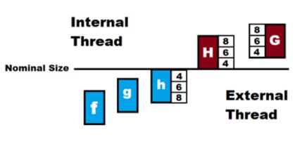
Figure 3 – ISO Thread Tolerances
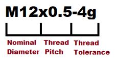
Figure 4 – Thread Spec Format
Considerations for Lens Mounting
Now that we have a basic understanding and common terminology to specify our lenses and mounts, fitting lenses and mounts should be straightforward, right?!! Well, let’s dig deeper into how the thread spec applies to lenses and the potential challenges that can arise. The threaded board-mount method of mounting lenses is common, convenient, and lends itself well to the universal fitment of off-the-shelf lenses. First and foremost, however, we need to remember that by definition threads must have some play in order to move with respect to each other. This “play” in the thread is the root of almost all of the potential fit challenges faced by customers in using a board-mount configuration. Even if the internal and external threads are specified properly, and the parts are within spec, the tolerance bands leave some room for variation. If the fit is too loose, it will result in excessive wobble and backlash, which can contribute to difficulty holding focal position, either in Z or in the tip/tilt axes. If thread-fit is too tight, it will lead to difficulty in reaching focus at the nominal back focal distance or may create debris due to excessive friction or mechanical interference in the thread.
Second, there is a bit of a disparity between mechanical specifications and optical specifications to consider. While typical thread tolerances (and lens mechanics, for that matter) are often measured in tenths or hundredths of millimeters, optical focal length tolerances are typically measured in thousandths (microns). This means that the tolerance bands (Figure 3) for specifying thread may not be as precise as seemingly necessary to maintain optical tolerances for a given use-case. Luckily, however, threads are continuously variable, and as long as there is no excessive wobble or backlash between the threads, it is still a very precise way to focus a lens. Let us take a simple example: If the depth of focus of a lens is +/-10um and the pitch is 0.5mm, this means that each 360° revolution moves the lens 500um. So +/-10um is 1/25th of a turn, or 14.4°, which is easily resolvable in practice. Yet, if there is excessive space between the threads, one can clearly see that the amount of play in the threads could easily overshadow this number and exceed the depth of focus of the lens, making fine-focus difficult.
The third consideration is the materials themselves. While any common material may work well for either the mount or the lens with proper fitting, there are some considerations here as well. Thermal performance requirements aside metals are relatively incompressible and metal-to-metal fitment can be tricky. Tightly matched metal parts tend to create debris or galling and slightly looser tolerances may be necessary to achieve the proper fit; something to keep in mind! Metal-on-plastic on the other hand, works well in most instances and can generally be a bit more snug, but can also create excess debris or “wedging” if fit too tightly. Finally, plastic-on-plastic is a relatively forgiving configuration in general but may have second-order thermal-stability limitations to consider.
For all of the above reasons, you will often see fitment pairings of h and G for off-the-shelf lenses. This ensures at least some gap exists (worst case) in order to avoid the possibility of a line-to-line fit while maintaining a reasonably tight match. These are also not the only considerations depending on the application, but these three are common to a majority of use-cases.
So What is the Answer and are There Other Options?
We can now see that the seemingly humble thread is much more complex than it appears; at least as it applies to lenses. So, what can be done to mitigate any risks associated with assembling and focusing board mount lenses?
- Engineering and support. We’ve hopefully demonstrated that mounts are not trivial, so let Sunex help you match the proper mount to the lens you selected. As alluded to above, there are a number of other case-specific considerations that Sunex can help you work through. Sunex has a variety of mounts for exactly this reason, and can help you pick the right one! By the way, it’s always a good idea to use a mount from the same supplier you purchase the lens from. There are also a number of “best practice” techniques for focusing that Sunex can help walk you through.
- Sunex can build a sub-assembly for you. For mass-production applications, let Sunex do the hard part! Sunex can assemble the lens to the mount and check for fit at your nominal focal position. Not only does this ensure a good fit, but because Sunex assembles, inspects, and packages everything in a cleanroom, it will typically reduce debris substantially at final assembly on your sensor board.
- Precision Mounting Concept. Do you need to up your alignment game in addition to just getting a good fit and focus? As we discussed above, threads must have some play in order to avoid excessive friction and the problems that come along with it, but too much play can ruin your image quality. Sunex’s Precision Mount Concept can reduce tip and tilt by up to 50% while simultaneously reducing reliance on thread fit, thus avoiding the need for tight tolerances and individual fitting. The key is in the matching of lens design to mount design. While several off-the-shelf Sunex lenses already have this feature, Sunex can customize any lens in our portfolio to be compatible with our Precision Mount designs.
- Finally, as resolution goes up and pixel pitch goes down, precision alignment becomes paramount. In rough terms, above 5MP resolution and/or below 2µm pixel pitch, threads and their associated tolerances begin to reach the limits of the precision required for best optical performance. In this regime, Active Alignment (AA) may present the answer. Sunex has a range of technologies to actively align our lens to your chosen sensor, taking the thread completely out of the equation. This process is typically most suitable for mid-to-high volumes and high resolutions, but depending on the use-case, it may add value for a multitude of use-cases. More information is included in one of our previous blog posts on AA.
Please reach out to Sunex using the Contacts link above if you need assistance with properly fitting, aligning, and focusing a board-mount lens and mount.

