1. Introduction
1.1. Background
How does sensor CRA affect lens design complexity and image quality?
High CRA sensors (CRA greater than 25 degrees) were developed to enable mobile phone cameras. The driving factor for high CRA sensors is the requirement of low z-height for the lens stack in mobile phone form factor. As shown by this paper, there are significant drawbacks of utilizing high CRA sensors for applications where a short z-height and compactness are not as important as that in a mobile phone use case.
It is advantageous to use lower Chief Ray Angle (CRA) sensors for high-performance imaging applications for the following benefits:
- Compatibility with Higher Performance Lens Designs: Lower CRA sensors improve compatibility with higher performance lens designs, where chief rays arrive at the image plane close to parallel to the optical axis. By aligning the sensor’s CRA with the lens’s exit pupil position, the system can achieve more uniform illumination across the image plane and reduce distortion variation.
- Improved Quantum Efficiency (QE) and Light Collection: Each pixel on a CMOS sensor typically has a microlens array to focus incoming light onto the photodiode. When light strikes at a high angle (high CRA), a significant portion can be reflected, refracted inefficiently, or even directed into an adjacent pixel. Lowering the CRA ensures light strikes the microlenses and photodiodes more perpendicularly, allowing for more efficient light capture, increasing overall QE, especially at the edges of the sensor, and improving low-light performance.
- Reduced Pixel Crosstalk: High CRA can lead to light intended for one pixel being absorbed by an adjacent pixel, causing reduced image sharpness. A lower CRA inherently reduces this likelihood by ensuring light enters the pixel more directly, minimizing “spillover” and resulting in cleaner images with higher signal-to-noise ratio (SNR).
- Improved Image Uniformity and Color Shading Correction: High CRA can result in significant micro lens array vignetting and color shading (radial color shifts) as off-axis pixels receive less light or color filters become less effective at oblique angles. Reducing the CRA improves the inherent uniformity of illumination and color response across the sensor, simplifying post-processing and leading to a more consistent, higher-quality image.
1.2. Problem Statement
What happens when the lens CRA does not match the sensor CRA?
While designers strive for optimal image quality, the choice of sensor CRA can fundamentally alter the demands placed on the accompanying optics. This paper seeks to answer an important question in optical system design: How does the Chief Ray Angle (CRA) of a CMOS sensor influence the optical design performance and physical dimensions of a lens system designed for the same spec?
A significant mismatch between the sensor’s CRA acceptance and the lens’s chief ray delivery can lead to critical image quality degradation, including vignetting, severe color shading, reduced overall quantum efficiency, and increased pixel crosstalk, particularly at the image periphery. While some of these artifacts can be mitigated through digital image processing, such solutions often come at the expense of computational overhead, increased noise, or compromises in real-time performance. Furthermore, in an era demanding ever-smaller and higher-performing imaging modules for applications ranging from consumer electronics to advanced industrial vision systems, understanding the relationship between CRA and physical lens dimensions is crucial for achieving optimal miniaturization, cost-effectiveness, and manufacturability without sacrificing needed optical quality. This paper aims to provide a quantitative comparison to guide more informed sensor and lens selection decisions.
1.3. Method
This study considers CMOS sensors across two common diagonal formats: 1-inch (approximately 16mm diagonal) and 1/2.5-inch (approximately 7mm diagonal). For each format, two distinct Chief Ray Angle (CRA) requirements are examined:
- For the 1/2.5-inch diagonal sensor (Case 1), cases with a high CRA of 40∘ and a low CRA of 7∘ are investigated.
- For the 1-inch diagonal sensor (Case 2), cases with a high CRA of 26∘ and a low CRA of 8∘ are analyzed.
For each case, we created two lens designs: a high CRA one and a low CRA one. These lens designs will be analyzed and compared based on their optical performance metrics, including Modulation Transfer Function (MTF), distortion, relative illumination (RI), lateral color over field, and longitudinal color over aperture. Furthermore, key physical dimensions, such as the total track length (TTL) and front lens diameter, will be compared between the two lens designs corresponding to each sensor format. To ensure a meaningful comparison, all lens designs for a given sensor format will be constrained to have the same number of lens elements, the same F-number (F/#), and to cover an identical field of view (FOV).
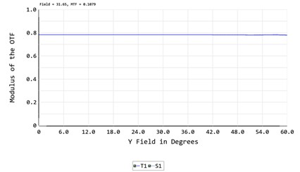
Since all practical designs have residual uncorrected aberrations, it is useful to review the theoretical maximum performance achievable for each CRA configuration assuming all aberrations are absent. We construct an ideal paraxial lens model in Zemax. The ideal lens model allows us to determine the upper limit of achievable MTF and RI for each case. High CRA version of each case shows that even if all aberrations can be perfectly corrected the maximum achievable performance are lower in the higher CRA versions.
2. Comparison for Case 1: 1/2.5-inch Diagonal Sensor
Case 1 of this study investigates the impact of CRA on optical design performance for a 1/2.5-inch diagonal CMOS sensor. The common specifications for the two lens designs considered within this case are as follows:
- Field of View (FOV): ±60∘
- F-number (F/#): 2.5
- Wavelength Spectrum: 435 nm to 656 nm
- Chief Ray Angle (CRA) Conditions:
- High CRA: 40∘
- Low CRA: 7∘
- Number of Lens Elements: 6 (fixed for both designs in this comparison)
The primary design goals for both lenses in Case 1 include maximizing the Modulation Transfer Function (MTF) performance, with comparable optical distortion, and minimizing variation of illumination across the entire field.
Table 1A. Two CRA Design Examples Comparison for Case 1
| Case 1 for CRA of 7 deg | Case 1 for CRA of 40 deg |
| TTL 40mm; Front Diameter 18mm | TTL 7.4mm; Front Diameter 4mm |
 |  |
| Max CRA 7 deg | Max CRA 40 deg |
 |  > > |
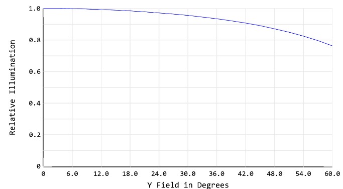
| RI over field | RI over field |
 |  |
| Field curvature over field | Field curvature over field |
 |  |
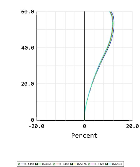
| Distortion over field | Distortion over field |
 |  |
| Lateral color between 435-650 nm over field | Lateral color between 435-650 nm over field |
 |  |
| Longitudinal Color over aperture | Longitudinal Color over aperture |
 |  |
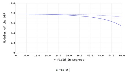
| MTF at 120LP/mm over field | MTF at 120LP/mm over field |
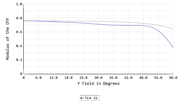 |  |
Table 1B. Two CRA Paraxial lens model Comparison for Case 1
| Paraxial model for case 1 CRA 7 deg | Paraxial model for case 1 CRA 40 deg |
 |  |
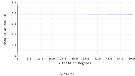
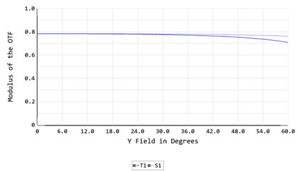
| MTF at 120LP/mm over field | MTF at 120LP/mm over field |
 |  > > |
| RI over field | RI over field |
 | 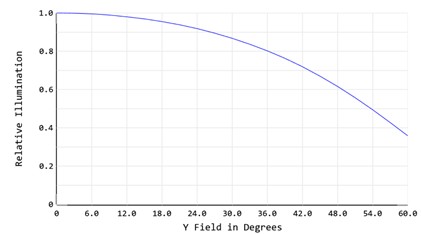 |
3. Comparison for Case 2: 1-inch Diagonal Sensor
Case 2 of this study investigates the impact of CRA on optical design performance for a 1-inch diagonal CMOS sensor. The common specifications for the two lens designs considered within this case are as follows:
- Field of View (FOV): ±40∘
- F-number (F/#): 2.8
- Wavelength Spectrum: 435 nm to 656 nm
- Chief Ray Angle (CRA) Conditions:
- High CRA: 26∘
- Low CRA: 8∘
- Number of Lens Elements: 6 (fixed for both designs in this comparison)
The primary design goals for both lenses in Case 2 include maximizing the Modulation Transfer Function (MTF) performance, with comparable optical distortion, and minimizing variation of illumination across the entire field.
Table 2 A. Two CRA design examples comparison for Case 2
| Case 2 for CRA of 8 deg | Case 2 for CRA of 26 deg |
| TTL 60mm; Front Diameter 22mm | TTL 14.7mm; Front Diameter 5mm |
 |  |
| CRA over field | CRA over field |
 |  > > |
| RI over field | RI over field |
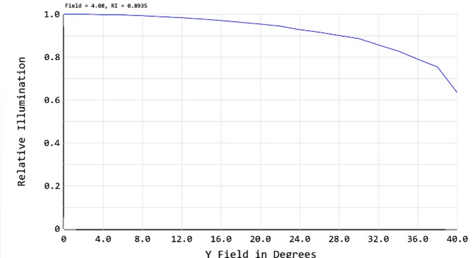 | 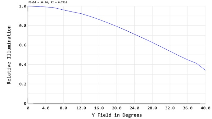 |
| MTF at 120LP/mm over field | MTF at 120LP/mm over field |
 |  |
Table 2 B. Two CRA Paraxial model comparison for Case 2
| Paraxial model for case 2 CRA 8 deg | Paraxial model for case 2 CRA 26 deg |
 |  |
| MTF at 120LP/mm over field | MTF at 120LP/mm over field |
 |  |
| RI over field | RI over field |
 |  |
4. Results and Analysis
How do I choose a lens that matches my sensor’s CRA specification?
4.1. Physical Dimensions: Total Track Length (TTL) and Maximum Lens Diameter
The main advantage of high CRA designs can be clearly seen from physical dimension differences. Both the total track length (TTL) and the front diameter of the lens are significantly smaller for the high CRA design compared to the low CRA design.
The larger sizes for low CRA designs are primarily driven by the requirement for near-telecentric imaging conditions. For such a design, the exit pupil effectively resides at or near infinity, necessitating that chief rays strike the sensor close to perpendicularly. This condition mandates that the physical aperture stop be located approximately at the focal point of the rear lens group. To minimize pupil aberrations induced by this rear group and to maintain a close-to-linear variation of CRA with image height, the focal length of the rear lens group must be sufficiently large. These factors prevent the miniaturization of the rear lens group, contributing to a longer overall lens.
The front lens group in the low CRA design plays a crucial role in adapting the wide field of view from the object space to a smaller, more controlled angular range for the rear lens group. This function, coupled with the constraint of maintaining a small chief ray angle at the physical stop for aberration correction, results in increased complexity and length for the front lens group. Consequently, the combined requirements for the front and rear groups lead to the low CRA lens being much longer and wider than its high CRA counterpart.
Conversely, in a high CRA design, the lens group following the aperture stop (the rear lens group) has less stringent requirements for bending the chief ray of the maximum field. The physical stop can be positioned much closer to the rear lens group. Furthermore, if the overall field of view (FOV) of the lens is high and comparable to the sensor’s maximum CRA, the front lens group needs to perform less angular adaptation for the rear group, allowing for a simpler and more compact front-end structure.
4.2. Chief Ray Angle Distribution
The variation of CRA versus image height is more linear in the low CRA design, whereas the high CRA design exhibits more significant non-linearity. The aggressive correction of field curvature and astigmatism within the limited space of the rear lens group in high CRA designs, often employing highly aspheric elements, inherently leads to greater non-linearity in the chief ray angle as a function of image height.
4.3. Relative Illumination (RI)
The relative illumination (RI) of the low CRA design rolls off much more gently than that of the high CRA design, and the RI at the maximum image height is considerably higher in the low CRA case. This observation is a direct consequence of the cosine fourth law, which dictates that RI decreases as the chief ray angle increases. The lower CRA of the design inherently minimizes these illumination losses. Additionally, entrance pupil expansion in the low CRA design, where the more complex front lens group increases the off-axis entrance pupil, contributes to a more uniform illumination profile across the field.
4.4. Modulation Transfer Function (MTF)
The MTF across the field of view for the low CRA design exhibits a slower roll-off and significantly smaller astigmatism than for the high CRA design. The variation of astigmatism over the FOV is particularly pronounced for the high CRA designs (e.g., 40-degree CRA). This directly correlates with the reasons detailed in the analysis of field curvature, astigmatism (Section 4.4), and spherochromatism (Section 4.7). Fundamentally, the improved MTF performance in low CRA designs is a consequence of the more favorable chief ray angles entering the rear lens group, which allows for better correction of off-axis aberrations and chromatic effects. The higher the chief ray angle incident on the rear group, the more challenging it becomes to achieve high and uniform MTF across the field.
5. Conclusion
This study demonstrates a clear trade-off between optical system compactness and imaging performance when selecting CMOS sensors with varying Chief Ray Angles (CRA). While higher CRA designs offer the advantage of achieving a smaller package size, enabling more compact camera modules, lower CRA designs consistently yield superior optical aberration correction and better align with inherent sensor characteristics, thereby ensuring significantly improved overall imaging performance.
A notable practical consequence of the aggressive optical designs often required for high CRA sensors is the difficulty in achieving effective athermalization across the field of view. This limitation can lead to significant performance degradation under varying temperature conditions.
Therefore, for applications where space constraints are not paramount and optimal image quality is the primary objective, a low CRA sensor is unequivocally the preferred choice. The benefits in aberration control, light collection efficiency, and image uniformity offered by lower CRA designs outweigh the packaging advantages of high CRA solutions in such scenarios.
Order COTS M12 lenses/s-mount lenses designed and manufactured by Sunex.