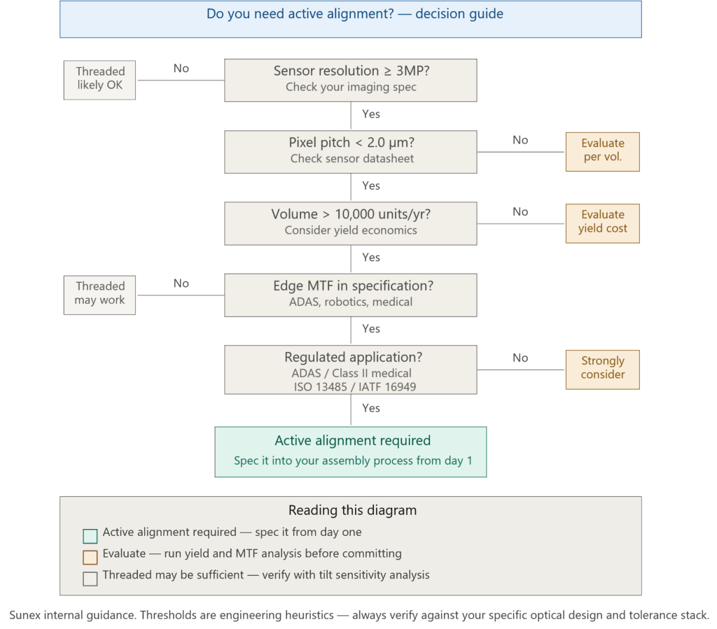
Active Alignment (AA) is a production assembly process in which a lens is positioned relative to a live, powered image sensor using real-time image feedback. It compensates for tilt and boresight errors that mechanical tolerances alone cannot control. We recommend evaluating AA for any system running 3MP sensors or above — and treating it as mandatory when pixel pitch drops below 2 µm, volumes exceed 10,000 units per year, or edge MTF specifications must be held at production yield. If those conditions don’t apply, manual threaded assembly may still be the right call.
We’ve had a version of the same conversation dozens of times over the years. A program is in late prototype. The center of the image looks great. But the corners are soft, inconsistently so — sometimes acceptable, sometimes not. The engineering team asks whether the issue is in the lens or the assembly. Then comes the follow-up question: do we actually need active alignment?
The short answer is: it depends on a specific set of conditions. This article walks through what active alignment is, why mechanical assembly alone eventually hits a wall, and how to decide whether AA belongs in your production plan — or whether you’re solving a problem you don’t have yet.

Why Does Lens Tilt Matter So Much More Than It Used To?
Ten years ago, a 1.3MP sensor with a 3.0 µm pixel pitch had a depth of focus wide enough to absorb a significant amount of assembly imprecision. The lens could be threaded into a barrel, manually focused against a resolution target by an operator, and locked in place — and in most cases the image was acceptable across the frame.
That tolerance stack no longer exists.
Modern embedded vision sensors — used in ADAS, robotics, industrial inspection, and medical imaging — routinely ship at 5MP, 8MP, even 20MP with pixel pitches of 1.4–1.8 µm. At those dimensions, the depth of focus drops to single-digit microns. A tilt of just 0.5° between the optical axis and the sensor plane shifts the focal plane at the image corner by several microns — enough to push MTF from compliant to failing within the same production lot.
The physics didn’t change. The sensor technology caught up to its limits.
Why Tilt Happens in Threaded Modules Tilt accumulates from four primary sources: (1) thread pitch backlash and ‘wobble’ as the barrel is rotated during manual focus; (2) variations in barrel and holder base flatness from machining tolerances; (3) PCB flatness variation, which changes with temperature and solder reflow; and (4) sensor glass height variation across wafer lots. Each source may contribute only tens of microns of error individually — but stacked up it regularly reaches 100–200 µm at the image plane, which is unacceptable at sub-2 µm pixel pitch. |
What Exactly Is Active Alignment — And How Does It Work in Practice?
Active Alignment is the process of adjusting the lens position — in up to six degrees of freedom — while the sensor is powered on and producing live image data. A test chart fills the field of view. The AA machine measures contrast or MTF at multiple zones across the frame simultaneously. Algorithms drive the lens carrier through sub-micron adjustments until a defined optimization criterion is met. Then the assembly is locked — typically with UV-cure adhesive.
The result is tilt precision typically below 0.3° — compared to the roughly 1.0° typical of a well-executed manual threaded process. That is a 3–4× improvement in angular error, and it compounds: better tilt precision means more consistent corner MTF, which means higher yield, which means lower unit cost at volume.
The key phrase is ‘live sensor.’ AA doesn’t rely on mechanical datums. It directly measures the optical performance of the complete module — lens, barrel, adhesive, sensor, and PCB together. The system compensates for all of those stacked tolerances simultaneously, not sequentially.
The Six Degrees of Freedom – A full AA system can adjust:
- X / Y translation — lateral centering of the lens over the sensor
- Z (focus) — axial distance to set focus distance
- θX / θY (tip/tilt) — the critical axes for corner sharpness
- θZ (rotation) — clocking the lens for sensors with non-square pixel arrays
Not every application requires all six. Many programs use a simplified four-axis AA (X, Y, Z, tilt) and skip θZ unless the sensor architecture or lens distortion pattern makes it necessary. Knowing which axes matter for your optical design is one of the first discussions worth having with your lens supplier before spec’ing the AA machine.
How Do You Know When Active Alignment Is Actually Required?
This is where we try to be direct rather than vague. AA adds cost — tooling, machine time, cycle time, and fixturing. It is the right answer for many programs, but not all of them. Here are the conditions that tip the scale.
- Resolution and Pixel Pitch
The 3MP threshold is a reasonable rule of thumb, but the more precise trigger is pixel pitch below 2.0 µm. Below that point, depth of focus is so shallow that manual assembly cannot reliably hold corner performance across a production lot. Some programs at 3MP with a 2.4 µm pixel pitch can still produce acceptable results with a carefully controlled threaded process — but yield will be lower, and you’ll spend engineering time sorting rather than shipping. - Production Volume
Manual alignment can produce a high-performing unit. It cannot do so consistently at scale. The sortation overhead — inspecting, reworking, or scrapping non-conforming modules — erodes any cost advantage of simpler assembly by the time you’re above 5,000–10,000 units per year. AA machines have high upfront cost but very low per-unit variability. The crossover point depends heavily on your spec tightness and acceptable yield target. - Edge MTF Requirements
If your application only cares about center performance — a document scanner, a simple barcode reader — a threaded module with a good lens can often hit spec. The moment your system specification requires edge MTF above, say, 40% at Nyquist across the full production lot, you are in AA territory. Wide-angle ADAS cameras, surgical imaging systems, and multi-camera machine vision arrays all fall into this category. - Regulatory and Qualification Context
If you’re sourcing lenses for a Class II medical device, this matters in a specific way: ISO 13485 process validation — IQ, OQ, PQ — requires you to demonstrate that your assembly process is capable and repeatable. Demonstrating process capability (Cpk ≥ 1.33 is the common threshold) on a manual threaded line for sub-2 µm sensor modules is extremely difficult. AA, with its built-in in-process measurement data, gives you a defensible validation record almost by design.
What Is ‘Favoring the Edge’ — And Why Does It Change the MTF Conversation?
Standard AA optimization maximizes on-axis MTF. The algorithm finds the position that produces the sharpest center image. This works well for most applications.
But a meaningful subset of programs — particularly wide-angle automotive cameras, drone imaging, and high-accuracy surveillance — have a problem: the objects that matter most are at the periphery. Pedestrians, traffic signs, license plates, anomalies in a production line. The center of the frame may contain sky or road. The corners contain the actionable information.
For these applications, AA can be configured to favor the edge fields during alignment. This means the optimization criterion is shifted toward outer-zone MTF, deliberately accepting a small reduction in center sharpness to pull corner performance up. The result is a module where the edge contrast meets the threshold required for reliable AI inference, even if the center MTF number is slightly lower than what an on-axis optimization would achieve.
This is only possible with active feedback. There is no passive assembly equivalent. A threaded module focuses the center — full stop.
Field Curvature and What AA Can (and Cannot) Fix
One question we get regularly: can active alignment correct field curvature? The answer requires a distinction.
AA can compensate for the tilt and axial offset introduced by mechanical tolerances — it can find the z-plane where both center and periphery are within acceptable MTF limits, effectively managing the impact of moderate residual field curvature. What it cannot do is change the fundamental optical field curvature of the lens design itself. If a lens has severe field curvature, no amount of AA will make it flat. The solution to that is optical redesign, not better assembly.
In practice, this means AA is most effective when paired with a lens that was designed with reasonable field flatness in the first place. Assembly precision and optical design are not substitutes for each other. They are multipliers.
How Do Active Alignment and Manual Assembly Actually Compare at Production Scale?
The table below captures the key parameters across the three most common assembly approaches. These are representative figures based on our production experience and published industry benchmarks from optical module assembly at contract manufacturers in Asia and Europe.
Parameter | Manual / Threaded | Fixed (Passive) | Active Alignment |
Alignment Method | Manual / Threaded | Fixed (Passive) | Active Alignment |
Tilt Precision | ~1.0° typical | 0.5–0.8° typical | < 0.3° achievable |
Suitable Resolution | Up to ~2MP | Up to ~3MP | 3MP–20MP+ |
Min. Pixel Pitch | > 2.8 µm | > 2.2 µm | < 2 µm (sub-pixel) |
Edge Performance | Inconsistent | Moderate | Optimizable |
Volume Scalability | Low–Medium | Medium | High |
Unit Cost (NRE + tooling) | Low | Medium | Higher upfront |
Rework / Yield Impact | High defect rate at scale | Moderate | Low at volume |
Table: Comparison of lens module assembly methods by key production and performance parameters. Tilt precision values are representative; actual results depend on equipment, process controls, and module design. NRE cost impact is highly program-specific.
What Are the Real Cost Tradeoffs — And How Do You Build the Business Case?
The cost conversation around AA usually starts in the wrong place. Engineering teams see the AA machine capital cost and conclude it’s expensive. That’s true at the unit level. The full picture is different.
Consider a 5MP ADAS module at 50,000 units per year with a 3% rework rate on manual assembly. At an average rework cost of $8–12 per unit (labor, test, handling), that’s $12,000–18,000 per year in rework overhead before accounting for scrap and field returns. Add supplier qualification audits and PPAP re-submission risk if your process drifts, and the ‘cheaper’ manual process starts looking expensive.
A Note on Caveat We want to be direct about one limitation: active alignment does not automatically guarantee a good module. It guarantees that the alignment is optimized — but if the lens design has inadequate MTF budget, if the sensor glass is tilted at the wafer level, or if the adhesive cure introduces stress that deforms the mount, AA will lock in a compromised configuration just as precisely as it would lock in a good one. AA is a process tool, not a design fix. The lens and the mechanical design still have to be right first. |
How Should You Approach the Active Alignment Decision Early in Your Program?
The single most common mistake we see is treating the AA decision as a late-stage manufacturing question. By the time a program is at pilot production and the team is debating whether to switch from threaded to AA, the PCB layout, lens barrel design, and adhesive process are already locked. Retrofitting AA compatibility into a module that wasn’t designed for it is expensive and often impossible without a re-spin.
Here is the sequence we recommend instead:
- At concept: Define your MTF specification across the full field — center and corners. If edge performance is in the spec, note it explicitly. This becomes a gating criterion for assembly method selection.
- At optical design: Work with your lens supplier to confirm the MTF budget at the nominal design. Understand the sensitivity of corner MTF to tilt. If a 0.3° tilt drops edge MTF by 15+ percentage points, you almost certainly need AA.
- At mechanical design: Design the lens mount and PCB for AA compatibility from the start. This means UV-cure adhesive access ports, adequate clearance for the AA fixture, and a flat sensor mount reference surface.
- At process definition: Decide whether to invest in in-house AA equipment or use a contract manufacturing partner with established AA capability. Understand their alignment optimization criteria — on-axis or edge-favoring — and make sure it matches your application.
- At qualification: Generate a measurement dataset across your qualification lot. MTF maps at center and corners, by unit, give you the Cpk data you need for process validation. This also serves as your baseline for detecting process drift in production.
What Does This Mean for Your Specific Application Area?
The AA calculus plays out differently by market. Here are the practical implications by segment:
- Automotive / ADAS
Automotive camera modules almost universally use AA at volume production, particularly for front-facing cameras above 2MP. ADAS functional safety requirements (ISO 26262) and camera system performance standards (ISO 16505 for CMS, UNECE WP.29 regulations) effectively require the process control that AA enables. Thermal cycling specs — operating range from −40°C to +105°C or wider — also mean the adhesive selection and cure process are as important as the alignment itself. - Medical Imaging
For Class II endoscopic, laparoscopic, or ophthalmic devices, AA has become the de facto standard above 2MP. The combination of small distal sensor packages (often below 4mm diameter), high sensor resolution relative to physical size, and regulatory documentation requirements make AA both technically and procedurally necessary. CE marking under MDR 2017/745 and FDA 510(k) submissions for Class II imaging devices will both benefit from the process traceability that AA-generated measurement data provides. - Industrial Inspection / Machine Vision
This market has more variability. An inline inspection camera at 5MP doing surface defect detection on a production line may require tight edge performance — AA is appropriate. A 3MP dimensional measurement camera where the measurement zone is always at image center may be fine with a controlled threaded process. The spec drives the decision. What we’ve noticed is that as AI-based inspection replaces rule-based algorithms, the demand for consistent edge performance increases — because neural networks train on the full frame, and inconsistent peripheral MTF creates batch-to-batch variability in model performance. - Robotics and Drones
Stereo camera systems for robotic navigation have an additional constraint: boresight accuracy between the two cameras. Relative tilt between a left and right camera pair directly degrades the accuracy of depth estimation. AA machines can align each camera individually and verify boresight simultaneously — something passive assembly cannot achieve repeatably. For depth accuracy better than 1% at operating range, boresight error below 0.2° between cameras is typically required, which puts this firmly in AA territory.
The Bottom Line: Match the Assembly Method to the Specification, Not the Other Way Around
Active alignment is not a premium option that makes any lens module better. It is a precision process that closes the gap between theoretical optical performance and repeatable production output — but only when the conditions warrant it.
If you’re running a 2MP module with a 2.8 µm pixel pitch at 2,000 units per year with relaxed edge requirements, a well-controlled threaded process is the right answer. If you’re designing a 5MP surgical camera or an 8MP ADAS front camera at 50,000+ units, the production case for AA is essentially closed.
The programs where we see the most pain are the ones in between: 3–5MP, moderate volume, tight-but-not-extreme specs. Those programs benefit most from an early, quantitative discussion about tilt sensitivity, MTF budget, and yield targets — before the mechanical design is locked.
TALK TO A SUNEX ENGINEER
If you’re trying to work out whether your current module design and pixel pitch combination genuinely requires active alignment — or whether a better mechanical design could get you there without it — we’re glad to walk through the tilt sensitivity analysis with you. That’s a real conversation, not a sales call. Reach out at sunex.com or through our Technology & Resource Hub.