Many customers use Sunex lenses in a custom housing unit, which is unique to their particular application. In many wide-angle lenses, especially fisheye lenses, it is important to understand where the rays of the maximum field of view for a specific sensor are located with respect to a reference datum on the lens in order to design a housing or hood that will maximize the field and not clip the rays. Understanding the concept of the entrance pupil is critical for this task.
What is the entrance pupil, and why does it matter for camera housing design?
By definition, the entrance pupil of a system is the image of the aperture stop as seen from the object side of a lens system. From a practical standpoint, the entrance pupil defines the ray bundle of light (typically approximated as a cone) that passes through the aperture stop to create an image. It is important to note that this position changes (along the optical axis in “Z”), based on the FOV, and hence the sensor dimension(s) in question.
The location along the optical axis (z-axis) of the entrance pupil is defined using the chief ray of a system. From an application standpoint, it is best to find the entrance pupil position using the edge ray at the maximum usable field angle in order to ensure that the extreme rays of a ray bundle will be imaged and not clipped.
How do I calculate the FOV cone for my lens at maximum field angle?
Below is an example method to characterize where this “maximum bundle” originates and thus locates the potential housing boundaries:
- Calculate maximum field of view. The FOV of the lens for the particular sensor that is being used can be calculated using Sunex’s online Optics Wizards.
- Depending on the exact application, the “maximum” field of view typically corresponds to the diagonal of the sensor. In case the image circle corresponding to the diagonal of the sensor is larger than the nominal image circle of the lens, assume the maximum field angle of the lens, and account for some overage.
- Please refer to the Sunex post on lens image circles for more information. The maximum image circle can be about 10-30% greater than the design/ nominal image circle depending on the type of lens and design.
- Contact Sunex to locate the entrance pupil location/ position (ENPP) OR the Clear Aperture (CA) of the Ray Intercept at L1S1, per your preference.
- A Sunex team member will find the entrance pupil location along the z-axis using the edge ray of the calculated maximum field angle. By specifying the location of this “edge ray entrance pupil” at a particular field angle, an effective cone can be drawn from that point along the optical axis, out towards the first lens element. This will give a direct visualization as to where the housing needs to stay within, relative to the first element.
- Alternatively, the intersection point of the edge ray with the first surface of the first element (L1S1) can be provided. This point provides the equivalent data from which the cone can be inferred and is sometimes preferred if you want to ensure the housing does not encroach on this point.
- In both cases, be sure to allow for tolerances, both for the housing and lens assembly, as well as optical tolerances. EFL’s and therefore FOV typically vary by a few percent in manufacturing.
- Answers will be in the format below (or similar).
Example
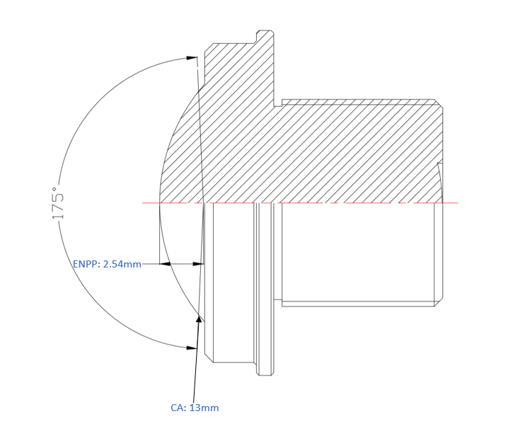
     •   Sensor: 1/4”, diagonal 4.5mm
     •   Lens: DSL215
     •   DFOV of DSL215 on 1/4": 175°
Answer
Edge ray entrance pupil position, with respect to (behind) L1S1, at FOV 175°(±87.5°): 2.54mm

Clear aperture  of lens, at L1S1, corresponding to edge ray of FOV 175° (±87.5°): 13mm
What happens if the camera housing blocks the edge rays of the lens?
When a camera housing blocks the edge rays of a lens, a phenomenon called mechanical vignetting occurs.
Mechanical vignetting occurs when the lens barrel, housing mount, or any aperture stop physically intercepts rays traveling at oblique angles (from off-axis scene points). The effects cascade:
1. Light falloff at field edges. On-axis rays pass through the full aperture area. Off-axis rays see a “crescent-shaped” effective aperture — part of the cone is simply cut off by the housing wall. Illuminance at the image edge drops as the square of the cosine of the chief ray angle (cos⁴θ law), but mechanical vignetting adds additional loss on top of the optical cos⁴θ that would exist even in a perfect barrel. (Smith, W.J., “Modern Optical Engineering,” 4th ed., McGraw-Hill, 2008)
2. Effective f-number increases at field edges. Because only part of the aperture cone reaches the sensor edge, the image there behaves as if shot with a slower lens — shallower depth of field and longer effective exposure are inconsistent across the frame.
3. Resolution degradation at field edges. The MTF (modulation transfer function) at the image periphery drops not just from aberrations but from the reduced number of contributing rays. Fewer rays = less spatial frequency information reaching the detector. (Fischer, R.E. et al., “Optical System Design,” 2nd ed., SPIE Press, 2008)
4. Color shading in some designs. If the vignetting is wavelength-dependent (e.g., the housing clips rays that have already passed through color-correcting elements), you get lateral color shifts toward the image periphery — a color cast that varies with field position.
5. In fisheye/ultra-wide lenses, the field of view is effectively narrowed. If the housing cuts edge rays before they ever reach the first optical element, the actual imaged scene is smaller than the lens’s designed FOV.