The lens image circle must equal or exceed the diagonal of your camera sensor — or you get vignetting (dark corners) that ruins image quality. If it is larger than needed, you are paying for optical coverage you are not using. Getting image circle matched to sensor format is the first step in any lens-sensor system design.
This article explains the relationship between image circle and sensor format, how to calculate FOV from these parameters, and common mistakes engineers make when pairing lenses with sensors.
Understanding the Relationship That Determines Your System's Field of View
In this white paper:
- What is a lens image circle, and why does it matter?
- How do I match a lens image circle to my camera sensor format?
- What happens if the image circle is smaller than the sensor?
- How does sensor format affect the field of view of my camera system?
- What sensor formats are commonly paired with M12 lenses?
- Conclusion
When engineers set out to build an imaging system, the conversation usually starts with field of view; how wide, how narrow, how much of the scene needs to be captured. From there it is tempting to look up a focal length, find a lens that matches, and move on. What often goes unexamined until something goes wrong is the relationship between the lens’ image circle and the physical dimensions of the sensor. That relationship is not a secondary detail. It is the foundation on which field of view, resolution, and image quality are all built.
This article walks through what image circle is, how it connects to sensor format, and why both must be understood together to arrive at a system that captures exactly what it is supposed to. Along the way, we look at how pixel pitch fits into the picture, how different coverage geometries create different requirements, and how seemingly minor specification mismatches produce problems that are easy to avoid once the underlying geometry is clear.
What is a lens image circle and why does it matter?
A lens does not project a rectangle. It projects a cone of light that produces a circular footprint on the image plane. Within that circle is the region where the lens delivers usable brightness, sharpness, and geometric accuracy. The diameter of that region is the image circle.
Every lens is designed around a specific image circle. During the design process, the optical engineer defines a maximum field angle or image height, and the lens is optimized to perform within that boundary. The result is a lens that performs well up to a certain diameter, and with diminishing returns beyond it. That diameter, doubled from the maximum image height, is the nominal image circle.
The nominal image circle is the specification you will find on a datasheet. It is the designer’s intended coverage diameter. In practice, the lens continues to project some usable light beyond this boundary — what Sunex defines as the true image circle, measured at the point where relative illumination falls to 10%. For wide-angle and fisheye designs, the true image circle typically extends 10–15% beyond the nominal value. For narrower field lenses, it can be 25–30% beyond. But that additional coverage is not guaranteed to be uniform or fully corrected, which is why the nominal value remains the proper basis for sensor compatibility decisions.
The image circle must fully cover the sensor diagonal, or the corners and edges of the captured image will fall into vignetting or hard clipping. This is a geometric constraint — it has nothing to do with whether the lens is functioning correctly.
When a lens is described as a “1/3-inch format lens,” that description is shorthand for the image circle it was designed to cover, in this case, a circle whose diameter matches the diagonal of a 1/3-inch sensor (6mm). Pairing that lens with a larger sensor means asking it to cover an area it was never designed for. The lens will not fail, but the sensor corners will.
How do I match a lens image circle to my camera sensor format?
Sensor format notation — 1/4″, 1/3″, 1/2″, 2/3″, 1″, and so on — is one of the more persistently confusing conventions in imaging. The fractions do not represent the width or diagonal of the sensor in inches. They are inherited from the era of vidicon vacuum tube cameras, where the fraction referred to the outer tube diameter. The actual active imaging area of a modern solid-state sensor is roughly two-thirds of what the notation implies. A 1/2″ sensor is not half an inch wide — its active area is closer to 6.4mm × 4.8mm.
This matters because the format name alone is insufficient for optical system design. What matters is the actual physical dimension of the active area, and specifically the diagonal, which is the distance from corner to corner across the sensor’s imaging surface. That diagonal is the number that must be matched against the lens image circle.
The table below lists common sensor formats with their actual dimensions and the minimum image circle needed to cover each format fully.
Sensor Format | Width (mm) | Height (mm) | Diagonal (mm) | Min. Image Circle |
1/4″ | 3.2 | 2.4 | 4.0 | 4.0 mm |
1/3″ | 4.8 | 3.6 | 6.0 | 6.0 mm |
1/2.5″ | 5.8 | 4.3 | 7.2 | 7.2 mm |
1/2″ | 6.4 | 4.8 | 8.0 | 8.0 mm |
1/1.8″ | 7.2 | 5.4 | 9.0 | 9.0 mm |
2/3″ | 8.8 | 6.6 | 11.0 | 11.0 mm |
1″ | 13.2 | 8.8 | 15.9 | 15.9 mm |
APS-C | 23.5 | 15.6 | 28.2 | 28.2 mm |
Full Frame (35mm) | 36.0 | 24.0 | 43.3 | 43.3 mm |
Table 1: Common sensor formats, their physical active area dimensions, and the minimum image circle required for full corner-to-corner coverage.
When working with a specific sensor, always pull the actual dimensions from the manufacturer’s datasheet rather than relying on the format label. Variations of a few tenths of a millimeter exist between manufacturers and product generations, and for tight image circle margins, those differences matter.
The minimum image circle column above represents the sensor diagonal, the hard floor for lens compatibility. In practice, specifying a lens whose nominal image circle exceeds the sensor diagonal by 5–10% provides meaningful margin against manufacturing variation, temperature-related shifts in the optical path, and focus changes across the working distance range.
Pixel Pitch: Resolving Power Beyond the Image Circle
Alongside physical format, pixel pitch is the other sensor specification that directly constrains lens selection. Pixel pitch is the physical size of each individual pixel, measured in micrometers. Modern imaging sensors range from below 1µm in compact consumer devices to 5µm and above in machine vision and scientific cameras.
A lens has a finite resolving power, and that limit is often expressed as a minimum pixel pitch, which means nothing more than the smallest pixel the lens can usefully resolve. If a lens is rated for a 1.67µm pixel pitch, it can resolve detail down to that level. The key asymmetry is this: a lens can work with a sensor whose pixel pitch is equal to or slightly larger than its rated minimum, but it cannot compensate for a sensor with a smaller pixel pitch than it is designed to resolve.
Scenario | Lens Pixel Pitch | Sensor Pixel Pitch | Result |
Well-matched system | 1.67 µm | 1.67 µm | Full resolution delivered |
Acceptable — sensor pixel slightly larger | 1.67 µm | 2.0 µm | Works well |
Mismatch — lens cannot resolve sensor pixels | 3.45 µm | 1.67 µm | Image appears soft |
Table 2: Pixel pitch compatibility between lens and sensor determines whether the full resolving capability of the sensor can be utilized.
Put simply: if the sensor’s pixels are finer than the lens can resolve, the lens becomes the bottleneck. The image will appear soft regardless of the sensor’s megapixel count. Selecting a lens whose pixel pitch specification matches the sensor, or runs slightly finer, ensures the sensor’s resolution is not being wasted. The applications engineers at Sunex can provide the minimum pixel pitch a lens can resolve upon request, making direct comparison to sensor specifications straightforward during the selection process.
What happens if the image circle is smaller than the sensor?
Field of view is the angular extent of the scene that the imaging system captures — stated as horizontal FOV, vertical FOV, or diagonal FOV. It is the central performance requirement for most imaging applications. And yet it is not a property of the lens alone. It is a property of the combination of lens and sensor.
The same focal length produces a different field of view on every sensor format. A 6mm lens on a 1/3″ sensor delivers roughly 44° horizontal field of view. The same 6mm lens on a 1″ sensor delivers roughly 75°. Move that lens to an APS-C sensor and the horizontal FOV expands further still. The lens has not changed, what has changed is the size of the rectangular window being cut from the image circle.
Field of view is a system specification, not a lens specification. Quoting a focal length without specifying the sensor format it is paired with leaves the actual field of view undefined.

Figure 1: Illustration of two systems with the same sensor format, the same lens EFL, but two different lens image circles.
This is one of the most common sources of specification confusion in imaging system procurement. A lens that delivered the right field of view on one project gets carried over to a new project using a different sensor, and the coverage angles change completely. The lens is doing what it always did; the sensor format is doing something different with it.
The underlying relationship is straightforward: a wider sensor dimension or a shorter focal length produces a wider field of view. A narrower sensor or a longer focal length produces a narrower one. This applies independently to the horizontal and vertical axes, which means changing the sensor format changes both FOV values simultaneously, in proportion to the change in physical sensor dimensions.
Coverage Mode: What Part of the Image Circle Is the Sensor Using?
Beyond the simple question of whether the image circle covers the sensor diagonal, there is a more nuanced question about how the image circle and sensor geometry relate to each other. Depending on the application, the answer changes what counts as an adequate image circle.
When the image circle is larger than the sensor diagonal (overfill) the sensor sits entirely within the optimized zone of the lens. Every pixel on the sensor receives well-corrected, uniformly illuminated light. This is the most robust configuration and the one that provides the most margin against real-world variation.
When the image circle matches the sensor diagonal precisely (full frame coverage) the sensor corners land right at the edge of the image circle. The lens is performing at its design limit at those corners, which demands a well-controlled design and careful manufacturing. This configuration is common in high-resolution industrial and broadcast lenses, where the sensor is as large as possible and the lens must be optimized all the way to the corner. Sunex’s large-format lens series, designed for 1″, APS-C, and full-frame sensors, addresses exactly this requirement, maintaining controlled MTF performance out to a 43mm image circle diameter.
When only the horizontal dimension needs to be covered (full horizontal coverage) the image circle may be smaller than the sensor diagonal, as long as it spans the full width. The corners of the sensor fall outside the image circle and are dark, but the horizontal field of view is fully captured. This configuration is used in some panoramic and wide-field surveillance applications where the vertical extent of the scene is less important than the horizontal sweep.
The most demanding configuration from an image circle standpoint is circular fisheye containment, where the entire image circle, the complete 360° or 180° disk projected by the lens, must fit within the sensor boundaries. This requires the image circle diameter to be smaller than the sensor’s smaller dimension, not just the diagonal. A fisheye lens with a 5.6mm image circle, for example, needs a sensor whose height is at least 5.6mm for the full circular image to land entirely within the active area.
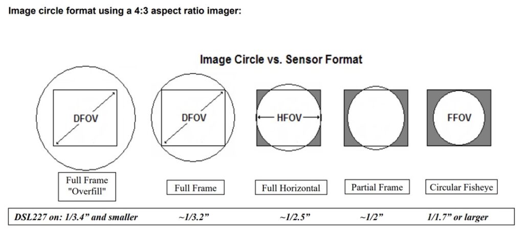
Figure 2: Image Circle vs. Sensor Format [Full Frame Overfill · Full Frame · Full Horizontal · Partial Frame · Circular Fisheye]
The same lens image circle produces different coverage geometries — and different effective fields of view — depending on sensor format and application coverage requirements.
How does sensor format affect the field of view of my camera system?
The coverage mode question becomes most consequential when it is not addressed during system design, and the mismatch shows up during integration. The following scenario illustrates how image circle and sensor geometry interact in a fisheye application, and the range of solutions available when the initial combination does not meet the coverage requirement.
Consider a system designed to capture a 180° × 180° full-circle fisheye image, with the complete circular image fully contained on the sensor. The selected lens has an image circle of 5.6mm. The selected sensor has an active area of 8.06mm × 4.54mm.
Furthermore, the lens itself produces an acceptable FOV across the horizontal and the diagonal, 173°, and for most applications, this is the standard goal. But this application requires the entire fisheye circle to sit inside the sensor boundaries. That means the image circle diameter of 5.6mm must fit within the shorter sensor dimension, which is 4.54mm vertically. It does not. The circular image overflows the top and bottom of the sensor, and the resulting footage shows the fisheye disk cut off at the vertical edges.
This is not a lens defect. The lens is projecting exactly the image circle it was designed to produce. The problem is that the sensor’s shorter dimension is smaller than the image circle diameter — a geometric constraint that no amount of refocusing, iris adjustment, or firmware tuning can resolve.
Once the geometry is understood, the paths forward are clear. The right solution depends on which element of the system can be changed and what the application can tolerate.
The first option is to find a lens with a smaller image circle that still achieves a comparable field of view. If a lens can produce a similar FOV with an image circle at or below 4.54mm, the complete fisheye disk will land within the sensor’s vertical span. The full circular image is preserved.
The second option is to use a lens with the same or larger image circle but a wider field of view, one that reaches the full 180° diagonal. In this case, the circular image still overflows the sensor vertically, but it does so at 180°: the horizontal edges of the sensor align with the 180° boundary of the fisheye, giving a usable semicircular or full-circle crop depending on the exact geometry. The clipping becomes intentional and predictable rather than arbitrary.
The third option is to keep the lens and change the sensor. The requirement is a sensor whose shorter dimension is at least equal to the image circle diameter, 5.6mm or more vertically. A sensor with an active area of 6.77mm × 5.66mm, for example, clears this threshold. The lens is unchanged; it now projects its full circular image within the sensor boundaries. This option must also consider the lens’ new FOV on the new sensor, for a change like this one will also affect it (as we previously covered in Part 3 of this article).
The fourth option is mechanical: rotate the sensor 90°. With the sensor’s longer dimension (8.06mm) now running vertically, the 5.6mm image circle easily fits within the frame. The circular image is fully contained vertically; the left and right edges of the sensor extend beyond the image circle horizontally, but for applications that only need vertical containment, this may be entirely acceptable.
Each of these options changes something different about the system, the lens, the sensor, or the orientation, but all of them stem from understanding the same underlying constraint: image circle diameter relative to sensor dimensions, driven by the specific coverage geometry the application requires. Sunex applications engineers work through exactly this kind of analysis as part of lens selection consultations, matching image circle specifications from the M12 and large-format portfolios to sensor geometry and application coverage requirements before any hardware is committed.
What sensor formats are commonly paired with M12 lenses?
Bringing together image circle, sensor format, pixel pitch, and field of view into a coherent system specification is less complicated than it might seem once the relationships are understood. The following framework consolidates the key decision points.
Start with the sensor’s actual physical dimensions.
Pull the active area width, height, and diagonal from the sensor manufacturer’s datasheet. It is important to not estimate the size from the format label. Measuring or looking up the actual values is strongly advised. For most applications, the diagonal is the minimum image circle your lens must provide for full-frame coverage.
Define what coverage geometry the application actually needs.
Full frame, full horizontal, overfill, or circular containment each place different demands on the image circle. Establishing this early prevents the common mistake of specifying a lens that covers the sensor diagonal but fails to meet a more specific coverage requirement that the application turns out to have.
Determine the required field of view and the focal length it implies.
State the FOV requirement in degrees, horizontal, vertical, or both, and calculate the focal length needed to achieve it on the chosen sensor format. Horizontal and vertical FOV are independent calculations based on the sensor width and height respectively. Because FOV and sensor format are linked, changing either changes the other: be explicit about both. The Optics Wizard at sunex.com/support can further help calculate the Effective Focal Length needed, depending on the FOV and sensor size.
Verify image circle coverage with margin.
Identify lens candidates that meet the focal length requirement and confirm their nominal image circle covers the required sensor dimension by at least 5–10%. The nominal image circle is the design target, and real lenses will fall within a tolerance band around it. Margin ensures the system stays within specification across that variation. Sunex publishes nominal image circle on all lens datasheets, and the Optics Wizard at sunex.com/support can further filter lens options by sensor format and coverage requirement, narrowing the candidate list quickly.
Match pixel pitch between lens and sensor.
Confirm that the lens’s pixel pitch specification is equal to or smaller than the sensor’s pixel pitch. A lens with a coarser pixel pitch spec than the sensor cannot resolve the sensor’s pixels, the image will be soft regardless of sensor resolution. This is a frequently overlooked constraint that is easy to check and worth verifying explicitly.
Validate with hardware.
Flat-field images across the full sensor area confirm uniformity. MTF measurements at the sensor corners confirm that the edge of the image circle is delivering usable sharpness. If the application operates across a temperature range or at varying focus distances, validate at the extremes. Datasheet specifications describe design intent; hardware measurements confirm actual system behavior. Sunex recommends testing production-representative lens samples rather than relying on nominal values alone, particularly for applications with strict uniformity or corner performance requirements.
Conclusion
Image circle, sensor format, and field of view are not three separate specifications to be checked independently. They are three expressions of the same underlying geometry. The image circle sets the boundary of what the lens can cover. The sensor format determines what portion of that coverage is captured and at what field angle. Pixel pitch determines whether the sensor can take full advantage of the lens’s resolving capability. Together, these parameters define the actual performance of the imaging system, not the performance of the lens in isolation.
The most common problems that arise from misunderstanding this geometry are also among the easiest to avoid: image clipping that is attributed to lens quality but is actually a coverage mismatch, soft images on high-resolution sensors paired with insufficient lens resolving power, and field-of-view errors that appear when a focal length is carried over to a different sensor format. In each case, understanding the lens-sensor relationship before hardware is selected eliminates the problem before it becomes one.
Sunex’s lens portfolio spans image circles from under 4mm through 43mm, covering sensor formats from 1/4″ through full frame, with pixel pitch specifications down to 1.67µm. The Optics Wizard and AI-powered Optics Consultant at sunex.com/support provide guided lens selection based on sensor format, coverage requirements, field of view, and working distance — and Sunex applications engineers are available to work through more detailed system specifications where standard tooling is not sufficient.
Related Resources
- Lens Image Circle — sunex.com/knowledge-center
- Choosing the Right Sourcing Strategy for M12 Lenses — sunex.com/knowledge-center
- Optics Wizard & AI-Powered Optics Consultant — sunex.com/support
- Large Format Lenses (1″, APS-C, Full Frame) — sunex.com/products/largeformat
- M12 Fisheye Lens Portfolio — sunex.com/products